
I'm going to attempt to give a quick rundown on the modification needed to run your own UMTS network on the cheap AT&T DPH-153 femtocells. I'll be able to make a software configuration guide in a later tutorial, but that's still something I'm ironing out, and I've had more than a few people ask what you need to do physically to get SSH access to the unit, so I wanted to be able to push this out as soon as possible. Much of my work has been derived from the original Osmocom issue thread, where the actual hard work of the hardware hacking got done, so I just wanted to compile all of this information into one place so you don't have to rebuild the instructions from alot of separate research notes (still alot of good stuff in that thread however, do check it out).
The modification you will need to do is enabling the SSH server on the unit and uploading your own key, since the root password is unknown. We have to do this by first gaining JTAG access to the unit, modifying the U-Boot environment to open a console on a serial port, and then enabling the SSH server and adding a key through the Linux command line. Given this, you will need:
- An AT&T DPH-153AT Femtocell (the 151 and 154 series also may work eventually, but there aren't reliable instructions for those units yet)
- A system capable of running the Osmocom 3G stack (configuration in a later tutorial)
- A JTAG debugger. For hobbyists without one, I recommend a cheap J-LINK Segger from AliExpress, mine I got for $21 total ($13 before shipping/tax). A few people have tried the PicoProbe project for Raspberry Pi including myself, it didn't work for me but it's also very likely I had a wiring problem.
- A UART bridge to interface with the serial output on the board. I used a cheap CH340 USB-to-UART device myself.
- Soldering equipment, there's one tricky point but the rest isn't awful. You can look at the pictures later in this post if you want to get an idea of what you'll be doing.
- Your choice of 8 wires to connect to the JTAG debugger, personally I used some 10cm DuPont jumper cables with one end stripped back and the other with a female connector for ease of connecting to the Segger. Keep the gauge low, otherwise you'll have a hard time soldering and risk lifting a trace on the board if there's too much strain (ask me how I know).
- (maybe) A long-handled flathead screwdriver, there's some prying you have to do and a little bit of brute force, unless someone can find a better way into these things.
Okay, let's open up the femtocell! Note: I'm going to put most of the example images in a Google Drive folder because it only lets me upload 5 attachments per post. I'll give the filenames which you can check out if you need.
Disassembly
The first thing you'll need to do is take out two screws from the bottom of the unit, you should be able to easily punch through the bottom sticker and grab them out. (see IMG_9459)
This next step is probably going to be tricky. We need to pry out the bottom orange piece, which is held SOLID by four big clips. We're going to need to pry and break them, again unless someone can find a gentler process for opening the unit. Check out IMG_9469 to see exactly what you're trying to separate (and notice the clips you'll have to break). Start by using something sharp to help get your prying tool wedged between the grey foot on the AT&T branded side of the unit and the orange bottom piece (see IMG_9461 and IMG_9462). Then, slowly make your way around, prying and releasing the orange tabs. When you get to one of the big clips like in IMG_9466, push in your prying tool and press down hard on one end to force the other end up and snap it, to get it free as shown in IMG_9468. You might be able to get away only doing this for two of them and carefully maneuvering the other end to keep it intact. Eventually, the bottom orange piece should be free (see IMG_9469). If you do this carefully, you can still get away with minimal exterior entry marks.
Good news, that was the hardest part of the disassembly! You might want to go now and dump the broken bits out the bottom of the unit and into the trash. With the bottom clips free, orient the AT&T branded side of the femtocell up, and carefully pry up the white cover on that side (see IMG_9472). Note that as you pry this side up, three anti-tamp jumpers will lift up with it and scatter as it frees itself. Some jumpers are fake with no conductive material and some are real, with AT&T's goal being that you wouldn't be able to accurately replace the jumpers. Don't worry about this, but try not to lose all the jumpers, as it seems the unit doesn't seem to like relearning the jumper configuration if it detects none of them are connected.
With this face off, there are four screws that need to be removed before the face on the other side can come off (see IMG_9473). After they are removed, you can repeat the same process with the other face (the 3G MicroCell branded side), keeping in mind the note about the anti-tamp jumpers (see IMG_9477 and IMG_9478). Next, use your screwdriver to pry back the plastic piece used to funnel light from the LED status indicators (see IMG_9479). It seems to be glued onto the frame of the unit as well as held in place by those nubs. It should go back just fine when time comes to reassemble it. After this is free, the board should be able to lift from the end where the plastic piece was and be pulled out of the frame (see IMG_9480 and IMG_9481).
Congratulations, the disassembly is complete!
 Now is the time to get your soldering and JTAG debugging equipment ready.
JTAG: Modifying the U-Boot Environment and Opening a Serial Console
The DPH femtocells were a very popular target for hackers when they first came out with the 151 series. Because of all the attacks, AT&T disabled the onboard serial console entirely along with the SSH service. To reenable the serial console (and then the SSH service), we have to modify the U-Boot environment stored in flash memory with our JTAG debugger.
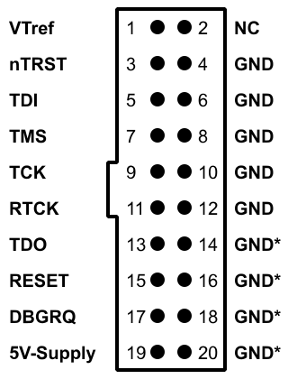
On the board, the JTAG header is located at PL1 (see IMG_9482, red box), next to the soon-to-be-enabled serial header at J3 (blue box). Here is the pinout of PL1, where pins 1 and 2 are closest to the edge of the board (credits to Neggles on the Osmocom thread):
Code: Select all
|-------|---|----|-------|
| X     | 1 | 2  | nTRST |
| GND   | 3 | 4  | TCK   |
| X     | 5 | 6  | TMS   |
| X     | 7 | 8  | TDI   |
| VTref | 9 | 10 | TDO   |
|-------|---|----|-------|
Before you start soldering, note that it is very easy to lift a trace/pad on this board! Try to minimize touching/bending any wires after you have completed soldering.
Connect nTRST, TCK, TMS, TDI, TDO, and VTref as normal, and GND to RTCK (the pinout page says this should be connected to ground if RTCK isn't available). We need to connect one more important pin, the RESET pin, for JTAG to work correctly. Unfortunately, this pin is not present on the header, so we have to use a makeshift pin on the bottom of the board that resets the CPU when tied to ground. On the bottom side, you will need to connect the TP186 trace (see IMG_9483, red arrow, and IMG_9500) to RESET on the debugger. I recommend finishing all the soldering on the front side, since comparatively they are easier joints, and then flipping the board and the debugger over so you can get a good joint on TP186 and make sure it doesn't fall off while working with the JTAG. @patch noted that you can also hot-glue the joints on PL1 to add extra stability/ruggedness while you work on TP186.
Here are some images for reference:
- IMG_1968_scaled.jpg (32.78 KiB) Viewed 55 times
- IMG_9500_scaled.jpg (40.46 KiB) Viewed 55 times
Code: Select all
sudo openocd -f openocd-dph153.cfgCode: Select all
Info : J-Link ARM V8 compiled Dec  1 2009 11:42:48
Info : Hardware version: 8.00
Info : VTarget = 3.300 V
Info : clock speed 9600 kHz
Info : JTAG tap: pc302.cpu tap/device found: 0x07b763a9 (mfg: 0x1d4 (Picochip Designs Ltd), part: 0x7b76, ver: 0x0)
Info : found ARM1176
Info : pc302.cpu: hardware has 6 breakpoints, 2 watchpoints
Info : starting gdb server for pc302.cpu on 3333
Info : Listening on port 3333 for gdb connections
Info : JTAG tap: pc302.cpu tap/device found: 0x07b763a9 (mfg: 0x1d4 (Picochip Designs Ltd), part: 0x7b76, ver: 0x0)
Info : found ARM1176
Warn : pc302.cpu: ran after reset and before halt ...
target halted in ARM state due to debug-request, current mode: Supervisor
cpsr: 0x600001d3 pc: 0x43e000c8
target halted in ARM state due to breakpoint, current mode: Supervisor
cpsr: 0x200001d3 pc: 0x06011004
Info : Listening on port 6666 for tcl connections
Info : Listening on port 4444 for telnet connectionsNow, we can send debugger commands through the telnet interface on port 4444, to connect:
Code: Select all
telnet localhost 4444Code: Select all
dump_image oem-env.bin 0x40040000 0x20000Code: Select all
Remove silent=yes entirely
Change consoledev to '/dev/ttyS0'
Change bootdelay to '99'
Then, use the mkenvimage utility (installable through apt on Ubuntu) to build the modified image with this command, replacing modified.txt with the file you applied the variable changes to:
Code: Select all
mkenvimage -r -s 131072 -o mod-env.bin modified.txtCode: Select all
flash write_image erase mod-env.bin 0x40040000We are done with the JTAG now, but I recommend keeping the wiring connected in case you have to re-flash the modified environment. Once we get serial access and try booting Linux, there's a chance it might overwrite our custom U-Boot environment, so save yourself the pain and keep it soldered until we get SSH access in case you have to reflash the U-Boot environment.
Serial Access and SSH Access
After we restart the unit, we should have a U-Boot console on J3, 115200/8N1 which we can use to interrupt the boot and gain access to a Linux terminal. J3 should be located just next to PL1, with this pinout (where pin 1 is the closest to the white silkscreened "notch"):
Code: Select all
1 = 3.3v
2 = device TX
3 = device RX
4 = GND- IMG_9531_scaled.jpg (34.32 KiB) Viewed 55 times
Code: Select all
setenv bootargs console=ttyS0,115200 root=/dev/mtdblock5 mtdparts=$mtdparts rw rootfstype=cramfs,jffs2 panic=1 init=/bin/bash
bootm 0x40080000
Code: Select all
mount -aCode: Select all
ssh-keygen -t rsa -b 1024Next, edit /var/ipaccess/nv_env.sh to look lis this:
Code: Select all
export ENV_VERBOSE_CONSOLE_ENABLED="TRUE"
export ENV_FIREWALL_DISABLED="TRUE"

export FS_VARIANT="224A"
export FS_LETTER=${FS:3:1}
export DEFAULT_UNHARDENED="TRUE" Code: Select all
sync && mount -o remount,ro /var/ipaccessCode: Select all
ssh -i id_rsa -o KexAlgorithms=+diffie-hellman-group1-sha1 -o PubkeyAcceptedKeyTypes=+ssh-rsa -o HostKeyAlgorithms=+ssh-rsa -o PubkeyAcceptedAlgorithms=+ssh-rsa -c aes128-cbc root@<DPH153_ADDR>Code: Select all
ip route add 192.168.157.184/30 via <DPH153_ADDR>
telnet 192.168.157.185Code: Select all
rmm_client 192.168.157.185 cs_cmd "echo 'root::0:0:root:/tmp:/bin/sh' >> /etc/passwd"Code: Select all
rmm_client 192.168.157.185 clear_tamper
cs_client set sys/learn_tamper 1
cs_client commitNow that we have SSH access and have relearned the tampers, you can start reassembling the unit if you wish.
To get the unit ready for Osmocom, we have to do a couple of little things over SSH before the Iuh link can be established. First, let's clear the tamper flag if it was ever set:
Code: Select all
rm /var/ipaccess/cisco/.tamper-flagNext, let's do some DMI configuration. We need to disable IPSec, set the HnbGw address, and update the NTP address. The NTP address update is important, because without it, it doesn't even attempt the HnbGw connection. Resolve the IP Address for 0.ipaccess.pool.ntp.org and keep it noted. In SSH, access the DMI console with:
Code: Select all
telnet localhost 8090Then, configure the following parameters:
Code: Select all
set ipsecEnable FALSE
set defaultNtpServer ("<RESOLVED NTP SERVER ADDRESS>")
set hnbGwAddress "<YOUR OSMO-HNBGW SYSTEM>"Code: Select all
action 2061
action 1216
action establishPermanentHnbGwConnectionThat should cover the physical modding and some of the basic configuration on the DPH-153 side of things, I hope this tutorial was helpful and do feel free to chime in if you have any comments/questions. Happy modding!

